Description
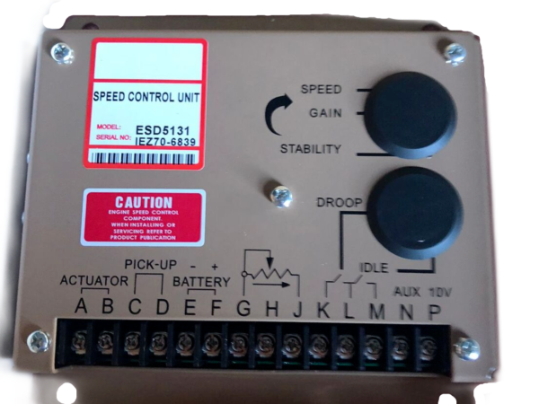
The ESD5500E GAC Speed Controller Unit is an all-electronic device designed to control engine speed quickly and precisely in response to transient load changes.
The ESD5500E controls a wide variety of engines in isochronous or droop mode when connected to a proportional electric actuator and magnetic speed sensor. The ruggedly built ESD5500E series is designed to withstand the engine environment. Light-Force variations are available.
Specifications of the ESD5500E GAC Speed Controller
Isochronous Operation ± 0.25 % or better
Speed Range / Governor 1 – 7.5 kHz Continuous
Speed Drift with Temperature ±1 % MAX
Idle Adjust Clockwise 60 % of Set Speed
Idle Adjust Counterclockwise Less than 1200 Hz
Droop Range 1 – 5 % regulation
Droop Adjust Maximum (K-L jumpered) 400 Hz ±75 Hz per 1.0 A change
Droop Adjust Minimum (K-L jumpered) 15 Hz ±75 Hz per 1.0 A change
Speed Trim Range ± 200 Hz
Remote Variable Speed Range 500 – 7.5 kHz
DC Supply 12 V DC and 24 V DC Battery Systems Transient and Reverse Voltage Protected*
Polarity Negative Ground (Case Isolated)
Power Consumption 50 mA continuous plus actuator current
Speed Signal Range 1.0 – 50 V AC
Speed Sensor Signal 1.0 – 120 V RMS
Actuator Current Range**
(77°F (25°C))
Minimum 1.0 A
Nominal 7.0 A
Peak 10.0 A
Vibration 1 g @ 20-100 Hz
Testing 100 % Functionally Tested
Ambient Temperature -40° to 85 °C [-40° to 180 °F]
Relative Humidity up to 95 %
All Surface Finishes Fungus Proof, Corrosion Resistant
Weight 1.20 lbf
When wiring ESD5500E Series controllers:
Use shielded cable for all external connections to the ESD controller.
One end of each shield, including the speed sensor shield, should be grounded to a single point on the ESD case.
Terminal A, B, E,and F should be 16 AWG or larger. Long cables require increased wire size to minimize voltage drops.
Battery positive (+) Terminal F should be fused for 15 A.
Magnetic speed sensors Terminals C and D must be twisted and or shielded for the entire length.
The gap between the speed sensor and the ring gear teeth should be smaller than 0.02 in usually backing out 3/4 turn after touching ring gear teeth. Speed sensor voltage should be at lease 1 V AC RMS during cranking.
If auto synchronization is used alone, not with a load sharing module, use a 3 Ω resistor between Terminal N and P to match the voltage between the speed control unit and the synchronizer.
When operating at the upper end of the control unit frequency range, add a jumper wire between Terminal G and J to increase the frequency range of the control unit over 7000 Hz.
Terminal P is used to supply +10 V DC regulated supply to accessories. No more than 20 mA of current can be drawn from this supply. Ground reference is Terminal G. A short circuit in this terminal can damage the speed control unit.
Do not over-tighten terminals. Torque to no greater than 9.0 in-lb ±2.5 [1.01 ±0.28 N∙m].


Reviews
There are no reviews yet.